VIBES & BMW Group
Comparison of methods between the classic acceleration-indicator and a mixed-indicator in-situ Blocked Force determination
The NVH-development cycle of vehicle components often requires a source characterization separate from the vehicle itself. This characterization is typically done using a test bench setup. In the context of frequency based substructuring and transfer path analysis, a component can be characterized using Blocked Forces. An exciting new development in this field is the mixed indicator Blocked Force determination, which uses both acceleration-based measurements and force gauges as indicators for the Blocked Force calculation. This study focuses on comparing the acceleration-based in-situ and new mixed indicator Blocked Force determination methods using measurements of an artificially excited electric power steering (EPS). Under real-life conditions on a test rig, the acceleration-based in-situ approach often shows limitations in the lower frequency range due to a relatively bad signal-to-noise ratio at the indicator sensors, while delivering accurate results in the higher spectrum. This is because the stiffness of the test-rig cannot be decreased arbitrarily due to the considerable loads that components experience in operation. The new in-situ hybrid approach was developed to compensate these deficiencies by using force gauges as additional indicators for the Blocked Force calculation. Force gauges have a higher signal-to-noise ratio in the lower frequency range than accelerometers on a relatively stiff set-up, which leads to a higher quality of the Blocked Forces using the mixed indicator method in the lower frequency range while still maintaining a high quality in the high frequency range. The study also investigates how many additional force gauges are needed to create higher Blocked Force qualities considering their higher costs. Results showed that depending on the complexity of the excitation of the active component, there will be diminishing return for additional force sensors. Thus, a cost-effective choice of force gauges requires a very good understanding of the active component.
Acceleration-based in-situ Blocked Forces
The acceleration-based in-situ approach is an innovative way to determine Blocked Forces at the interface $$ u_{2} $$. This approach relies on an inverse determination of Blocked Forces that are calculated based on accelerations $$ u_{4} $$ detected near the coupling point. In real-world applications, this approach has the major drawback of insufficient mobility of the substructure the accelerometers are applied to. This leads to low levels of signal-to-noise ratio in the lower frequency range. Despite this limitation, the acceleration-based in-situ approach is a promising way to measure and analyze Blocked Forces in various applications.
Mixed indicator Blocked Forces
The mixed indicator approach is an innovative way to compensate for the disadvantages of the acceleration-based in-situ approach. This approach relies on additional force indicators, which provide a significantly higher level of system description. The blocked forces are then calculated using the Transmissibility from the virtual point forces to the forces at the force gauges. Like this, the force sensors act as additional indicator responses, and the blocked forces are obtained as follows:
$$ f{{_{2}}^{bl}} = \left ( \begin{bmatrix}
\mathrm{Y}_{42}\\
\mathrm{T}_{42}
\end{bmatrix} \right )^{+}\begin{bmatrix}
u_{4}\\
g_{4}
\end{bmatrix} $$
Application to EPS-steering systems
Vehicles are defined by their comfort and driving dynamics. To create a modern steering system that addresses both, Electronic Power Steering (EPS) is often used. However, due to the high loads and complex components involved, NVH phenomena can occur. To reduce these effects, Blocked Forces of acoustically obtrusive and unobtrusive steering systems can be determined and analyzed in a test bench setup.
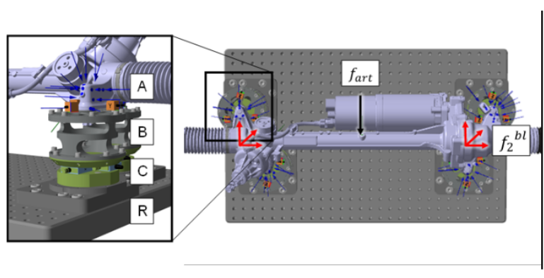
The EPS (A) is mounted to support structures (B) at the four connection points which are mounted to a structure (C) which is then mounted to the test bench (R). The indicator accelerations $$ u_{4} $$ are measured on the support structures close to the interface with the EPS (three triaxial sensors per connection point). The indicator forces $$ g_{4} $$ are measured in between the support structures and the test bench (three triaxial force gauges in a sandwich-structure (C) per connection point).
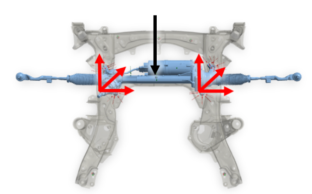
The system is excited with an impulse hammer in the middle of the EPS (artificial excitation). This excitation is then characterized by Blocked Forces in two 6-DOF Virtual Points, one on each side of the EPS.. The measured FRF $$ \mathrm{Y}_{42} $$, $$ \mathrm{T}_{42} $$ are from the Virtual Point at the interface 2 to the acceleration and force indicator positions, respectively.
Transfer Validation
To check the receiver independence of the calculated blocked forces, we perform a transfer validation. This relies on the comparison of a measured system response and a predicted response to the same excitation – here, an artificial excitation. The important point is that the Blocked Forces, which are used for the prediction, are calculated in a different test assembly as the measured validation.
Here, the Blocked Forces are determined on the beforementioned test bench and the validation measurement is done on an assembly of the EPS with a subframe. The artificial excitation was performed on the same position on the EPS for both measurements.
The Virtual Point Technology implemented in DIRAC enables the precise transfer of Blocked Forces from the Virtual Points of one test assembly to the Virtual Points of the other, which facilitates the transfer validation.
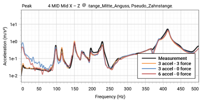
The two methods compared in this study had different results. The acceleration-based approach has high accuracy up to 500Hz, but not below 80Hz (blue). The mixed indicator approach uses three accelerometers and three force gauges per virtual point to get more accurate results (orange). The results of the hybrid method show significantly better results and match the prediction perfectly. However, the hybrid method also used additional sensors, and the impact of that extra information needs to be studied. When more accelerometers are used instead of force gauges, the results (red) are slightly better, but not enough to make a difference. This shows that the force gauges indeed add higher quality indicator data for the blocked forces than the accelerometers. The improvement is due to the better signal-to-noise ratio of the force indicator sensors compared to the acceleration indicator sensors.
This shows how force gauges can highly improve in-situ Blocked Forces on component test benches. This can be leveraged with the mixed indicator method which uses the force gauges as indicators in the blocked force calculations. This method is implemented and can easily be used in SOURCE.
Acknowledgements
The SAE technical paper of this case was written by Maximilian Hammer (HAW Landshut), Alexander Härtel (BMW Group) and Ron Reichart (VIBES.technology). The full paper can be found here.


