VIBES & Magna Steyr: Optimization of e-compressor noise
Dynamic substructuring methods allow experimental and simulative models to be coupled with one another. Substructuring can defuse the problem of missing model availability in concept phases, which is quite common, and the interior acoustics can be assessed at an early stage. To this end, Magna and VIBES.technology optimized the noise isolation concept of the electric climate compressor in the concept phase of a vehicle development project. It could be proven that the initial isolation design would have exceeded the interior noise target by 20 dB. Optimization of the substructured model made it possible to accomplish the noise target without additional decoupling or masses.
NVH design in early project phases
The electric climate compressor is a dominant source of noise in electric vehicles, as it is active in many operating states, for example, when controlling the battery and the vehicle’s interior temperature. Integration processes of compressors in cars usually start early in project concept phases. Once the thermodynamic requirements are established, it is necessary to design the installation space, the noise isolation, and airborne sound insulation of the compressor while meeting the acoustic goals.
A compromise must be found between component resonances caused by the road, structure-borne noise caused by the compressor operating forces, and the complex airborne sound radiation. Various isolation concepts and the need for airborne sound capsules for the compressor were examined as part of the virtual development phase of a vehicle project at Magna in Graz. At the component target level an important criterion is to compare the sound excitation of compressors from different manufacturers. Differences in their structure-borne sound excitation and the directly radiated air-borne sound were compared.
Modular NVH development through substructuring
A compact overview of the simulation methods used is given below, with reference to the literature.
Dynamic Substructuring
Vibration models of structures describe the relationship between applied dynamic forces and the resulting vibrations. They can be obtained by simulation (multi-body or FEM models) or experimentally (FRF measurement). Components under development are often simulated, as this allows design changes to be assessed quickly. Existing components with complex transmission paths are preferably modeled experimentally, as this is more precise and saves time-consuming modeling and validation. Dynamic substructuring can be used to couple multiple vibration models [reference]. If the “coupled” system consisting of two components A and B vibrates, two boundary conditions apply at their interface:
- Compatibility:
The vibrations at the interface between structure A and structure B must be the same. - Equilibrium:
The interface-forces act on structure A and structure B in the same magnitude and in opposite directions (principle of intersection).
In principle, these boundary conditions can be used to couple a variety of different models to simulate the dynamics of the assembled system. By coupling simulative and experimental component models, hybrid models of complex systems’ transmission paths are created.
Virtual Point Transformation
A practical challenge when creating experimental models is the correct measurement of all degrees of freedom at the interfaces. The Virtual Point Transformation is used for this purpose [reference]. Coupling points are described with six degrees of freedom: three translational and three rotational. Rotational degrees of freedom are necessary for a correct description of the dynamics in the higher frequency range [reference]. Several acceleration sensors and force excitations are placed around the coupling points for the creation of experimental models. The measured raw data is geometrically projected onto the Virtual Points in the DIRAC measurement software, and the model is checked for physical plausibility and measurement errors (see Figure 3).
Blocked Force TPA
With component-based TPA, noise and vibrations can be predicted on the virtual, sub-structured vehicle model in the early development phase [reference].
The “Blocked Forces” of a vibration source can be determined experimentally on a component test bench. The following thought experiment explains the principle (see Figure 1):
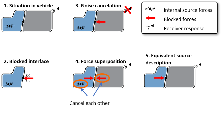
Figure 1: Schematic description of the Blocked Force principle
- Internal forces act in the vibration source (A). These also excite the receiver structure (B) via the interface connection, which generates a receiver signal.
- Blocked Forces are the forces that, when applied to the interface of source A, extinguish all vibrations there. They “block” the interface, like a fixed support.
- If the Blocked Forces were applied as external forces on the interface between A and B, they would also “block” any vibration downstream the interface. This means that there is no signal on receiver B (equivalent to the principle of “active noise canceling”).
- Due to the superposition principle in linear systems, the Blocked Forces can be applied to the interface with a positive and negative sign, without changing the response on the receiver. One simply adds “zero” to the equation. (Assumption: The internal source forces are independent of the receiver stiffness.)
- Since the Blocked Forces and internal forces cancel each other out on the receiver, the response on the receiver can equivalently be described by the (negative) Blocked Forces.
This is described in equation 1 (see [reference] for the formal derivation):
| $$ \mathbf{p}^\textrm{B}_3 = – \mathbf{Y}^\textrm{AB}_{32} \mathbf{f}^\textrm{bl}_2 $$ (1) | |
| $$ \mathbf{p}^\textrm{B}_3 $$ | simulated signal at the receiver (e.g. interior sound pressure) |
| $$ \mathbf{Y}^\textrm{AB}_{32} $$ | Transfer function of the coupled system AB from interface 2 to receiver 3 |
| $$ \mathbf{f}^\textrm{bl}_2 $$ | Blocked Forces |
Results
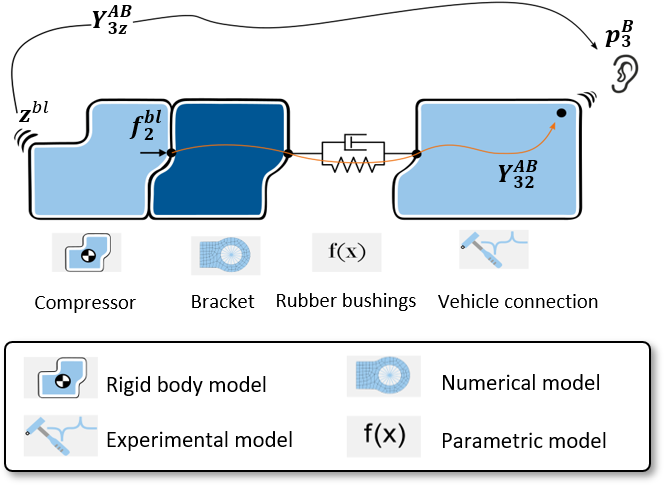
Figure 2: Schematic representation of the compressor isolation concept and the component models used
Hybrid simulation model
The compressor isolation concept is shown schematically in Figure 2. The compressor is connected to a bracket, which is connected to the vehicle’s electric drive train via three pressed-in rubber bushings. The modeling method with the best compromise between accuracy and effort is selected for the individual components. The compressor can be modeled as a rigid body due to its modal properties. FE modeling is selected for the bracket, which was done within COMSOL Multiphysics. The rubber bearings are still to be designed. They are described with simple parametric models, where axial and radial directions have different stiffnesses. Their geometric alignment is part of the parameterization. An experimental model of a similar reference vehicle is used for the complex transmission path from the electric drive train to the driver’s ear, since neither a prototype nor a numerical model of the project vehicle was available at this early stage. For this purpose, a 3D scan was created of the electric drive train. The geometry is imported in the DIRAC measurement software in order to place acceleration sensors, excitation points, and Virtual Points. The experimental vehicle model is created in DIRAC and checked for physical plausibility (see Figure 3 (a)). All component models were coupled through substructuring to simulate the transmission matrix from the compressor to the driver’s ear ($$ \mathbf{Y}^\textrm{AB}_{32} $$ in equation (1)).
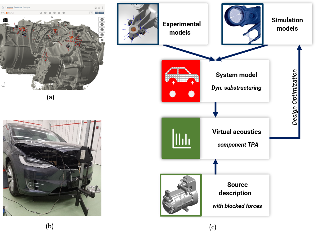
Figure 3: (a) 3D scan of electric drive train with compressor connection in DIRAC measurement software. Virtual Points for coupling are shown as orange spheres. (b) Artificial airborne sound source in the reference vehicle engine compartment. (c) Schematic workflow for optimizing the compressor isolation concept
Compressor Blocked Forces
The Blocked Forces $$ \mathbf{f}^\textrm{bl}_2 $$ of the structure-borne of the structure-borne noise source compressor are now required (see equation (1) and Figure 3 (c)). Two compressors were compared with one another: the project compressor and a series compressor that is already established on the market. For this purpose, they were freely suspended in an acoustic test bench and equipped with acceleration sensors, and then a controlled run-up was measured. The Blocked Forces of both compressors were determined inversely from their transfer function and operational vibrations [reference, Ch. 11].
Figure 4 (a) shows the norm of the translational Blocked Forces of project and series compressor during run-up. The project compressor introduces an approx. 2 dB higher structure-borne sound excitation into the system. Figure 4 (b) shows the individual translational components of the Blocked Forces of the project compressor (order filtered to the first order). It becomes clear that the two translational forces in the radial direction of the compressor, x and y, dominate the overall excitation. The operating forces increase approximately quadratically with the speed, which is typical for an unbalance excitation. This suggests using an imbalance value in [g x mm], calculated from the Blocked Forces, as a component target.
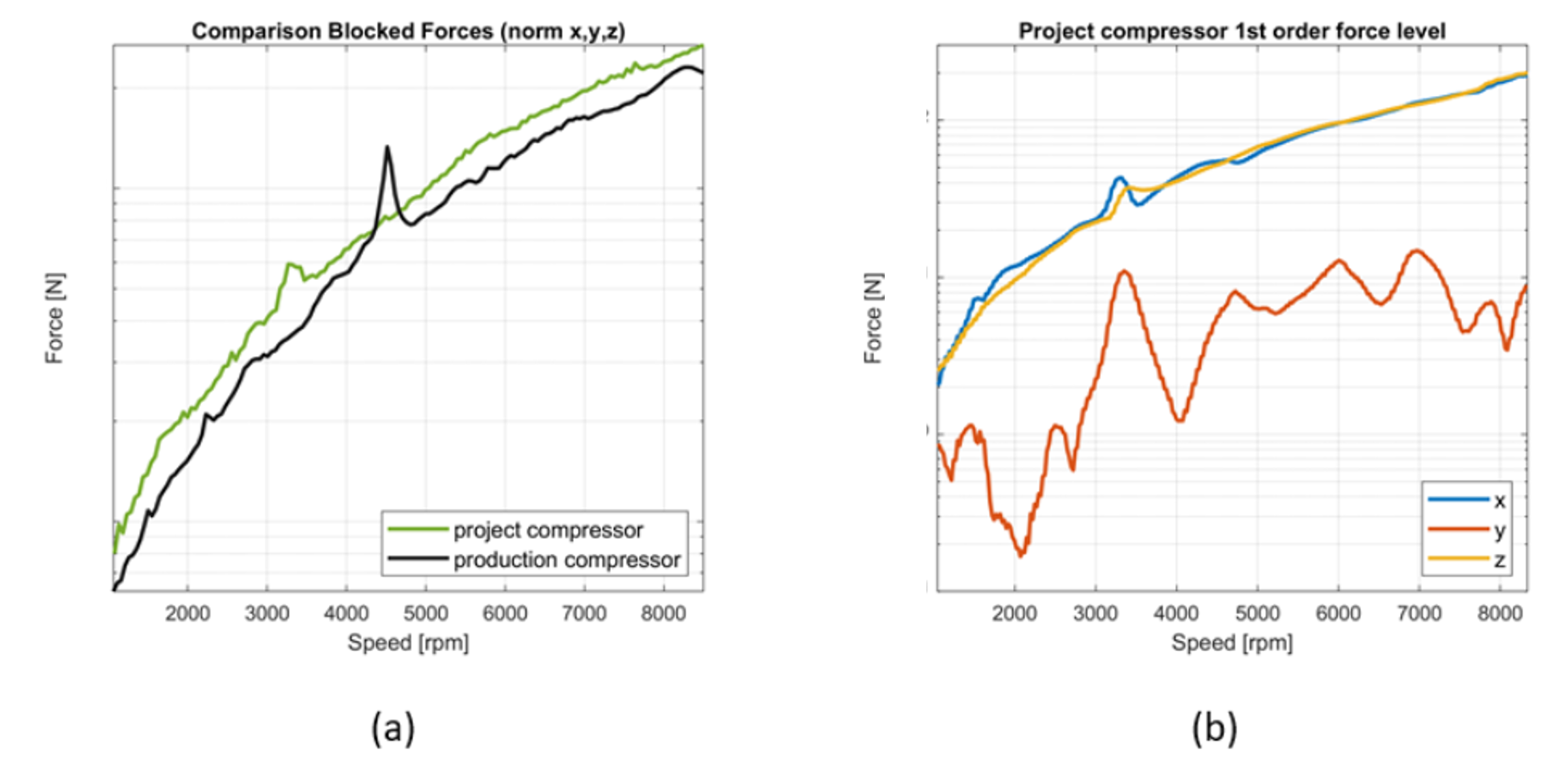
Figure 4: (a) Comparison of Blocked Forces project and series compressor, (b) order-filtered Blocked Forces for project compressor
Structure-borne noise optimization
The sound pressure in the interior can be predicted by equation (1). The transmission matrix of the system $$ \mathbf{Y}^\textrm{AB}_{32} $$ is simulated via substructuring. In this way, a virtual optimization can be carried out on the system. This workflow is shown in Figure 3 (c). In Figure 5, the sound level in the driver’s cabin for the initially planned isolation concept is shown in red and the noise target level of 38 dB (A) in gray. The initial concept would have exceeded the target by 15 to 20 dBA. The problematic speeds are caused by acoustic interior modes of the reference vehicle or resonances of the isolation concept. A parameter study showed that slight changes to the concept, such as additional masses or slightly modified bushing stiffness, do not provide sufficient leverage to meet the interior noise goals. A significant change in the bearing stiffness and topology was necessary. the operational deflection shapes of the compressor that it is possible to develop an isolation concept that absorbs the inertia forces of the compressor, such as by road excitation, with stiffer axial bearing directions. At the same time, the dominant imbalance operating vibrations of the compressor are decoupled from the vehicle by soft radial bearing directions. The interior noise level for the optimized isolation concept is shown in Figure 5 in green. With the optimized concept, the interior goals could be achieved without any additional decoupling levels or masses.
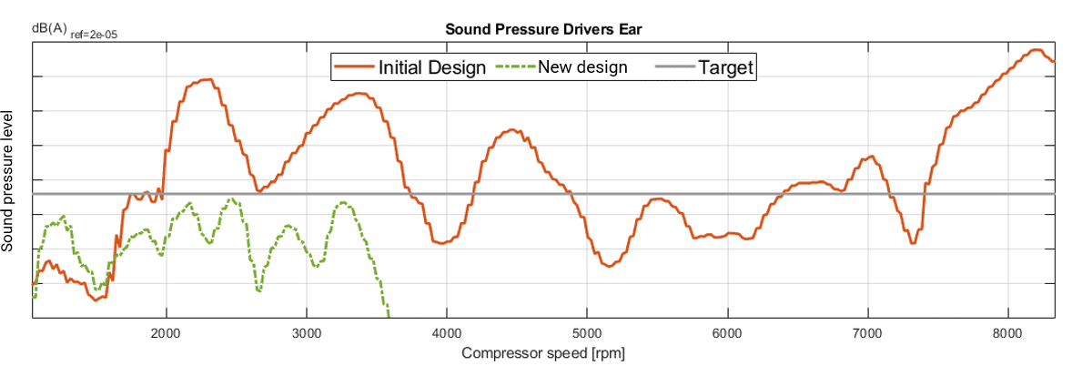
Figure 5: Prediction for structure-borne noise of initial and optimized isolation concept
Airborne sound
The compressor also emits airborne sound directly from its housing surface and via adjacent surfaces on the passive side of the screw-on points. Due to the existing decoupling, only the contribution of the compressor housing surface to the interior noise was considered. It was evaluated using an airborne sound TPA method. The airborne TPA principle can be seen as the uncorrelated equivalent of the component based TPA for the structure-borne noise (see [reference] and [reference, Ch. 10]. An acoustic surrogate source is used for source description. The acoustic source strength $$ \mathbf{z}^\textrm{bl}_{ } $$ [V] is determined on the component test bench from microphone signals, see [reference]. The airborne sound transfer function in the reference vehicle $$ \mathbf{Y}^\textrm{AB}_{3z} $$, is measured directly with sine sweeps of the surrogate source (see Figure 3 (b)). This allows the computation of the airborne sound contribution at the driver’s ear (see also Figure 2):
| $$ \mathbf{p}^\textrm{B}_3 = \mathbf{Y}^\textrm{AB}_{3z} \mathbf{z}^\textrm{bl}_{ } $$ (2) |
Figure 6 shows the airborne noise contribution from both compressors in the driver’s cab. The contribution for the project compressor is below the noise target, whereas the reference compressor leads to the target being exceeded due to a higher emission at approx. 5,800 [rpm]. There is therefore no need for encapsulation of the project compressor.
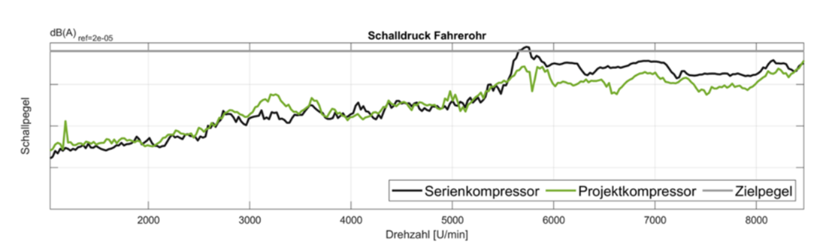
Figure 6: Airborne noise prediction for both compressors
Summary
More precise predictions are made in the early project phases by means of substructuring and component TPA so that potential concept errors can be identified and rectified. It is important for decision-making in projects that their impact can be efficiently reported directly at the driver’s ear.
VIBES Technology has implemented research results on these methods in user-friendly software. In a vehicle development project at Magna, it was thus possible to show that the project’s electric climate compressor introduces only minimally more structure-borne noise into the vehicle than a comparable reference compressor. The main excitation mechanism via the imbalance can be used as a supplier target variable. The isolation concept had not yet been examined for NVH and would have exceeded the cabin noise target by 20 dB (A). The isolation concept could then be optimized virtually in such a way that the target was achieved without additional masses or decoupling levels. It could also be shown that no air-borne sound capsule has to be included in the concept for the time being. Expensive adjustments to the sound insulation concept in late project phases can thus be avoided, and the vehicle developer gets a clear picture of critical transmission paths.
Acknowledgements
The authors would like to thank Walter Zipp and his colleagues from IPEtronik for their help in operating the compressors on their component test bench.