DIRAC
Test-Based Component Models, directly from Measurements
DIRAC is a high-quality FRF measurement and analysis software that helps you get the most out of your test data — faster and with fewer errors. Built on deep expertise in vibration science, it combines guided design of experiment, live and performant FRF measurements with deep quality insights, and immediate analysis to turn complex FRF testing into a reliable, efficient workflow.
Explore DIRAC
From design of experiment to model validation, DIRAC covers the full FRF measurement workflow on passive structures. It combines advanced measurement workflows with the Virtual Point Transformation (VPT) — a technology built on deep knowledge and strong implementation that transforms sensor-level FRFs into interface-level models, independent of sensor position and orientation. Built-in quality indicators at every stage — from design of experiment through to the final model — give engineers confidence that results are right before they reach downstream simulation. By directly linking high-quality test data with simulation models, DIRAC enables engineers to assess model accuracy, avoid common measurement pitfalls, and extract more value from every measurement.
Why Test-based Modelling Needs DIRAC
High-quality FRF measurements are the foundation of reliable test-based models — yet acquiring them is time-consuming, costly, and vulnerable to errors that only surface late in the workflow. Even experienced engineers can lose valuable insight through sub-optimal design of experiment, inconsistent measurements, or limited use of the data afterwards. DIRAC reduces these risks by helping you acquire trustworthy FRF data and extract more value from every measurement and model.
Typical challenges in FRF-based testing include:
- High effort and cost to set up and execute reliable measurement campaigns
- Strong dependence on user experience, increasing the risk of errors
- No feedback during measurement — problems surface only in post-processing
- Standard measurement approaches capture only translational degrees of freedom, leaving rotational contributions unmeasured and interface descriptions incomplete
- Difficulty translating raw FRF data into validated, reusable component models
- Gaps between measured results and the models simulation teams can actually use
DIRAC was designed to close these gaps — from design of experiment through to a quality-assured test-based model — in a single, integrated workflow.
Built for Modular NVH Engineering
DIRAC achieves this through a modern, intuitive software environment that guides engineers through the full FRF workflow, from experiment design to immediate analysis. By combining fast measurement workflows with built-in engineering intelligence and advanced vibration science, DIRAC reduces the likelihood of common mistakes while accelerating test execution. As a result, measured FRFs are immediately usable as high-quality input for a wide range of advanced NVH applications, including:
-
Source characterization
-
Blocked forces identification
-
Component TPA
-
Test-based simulation
-
Dynamic Substructuring
-
Hybrid Modular Modelling and simulation
-
Structural Modification
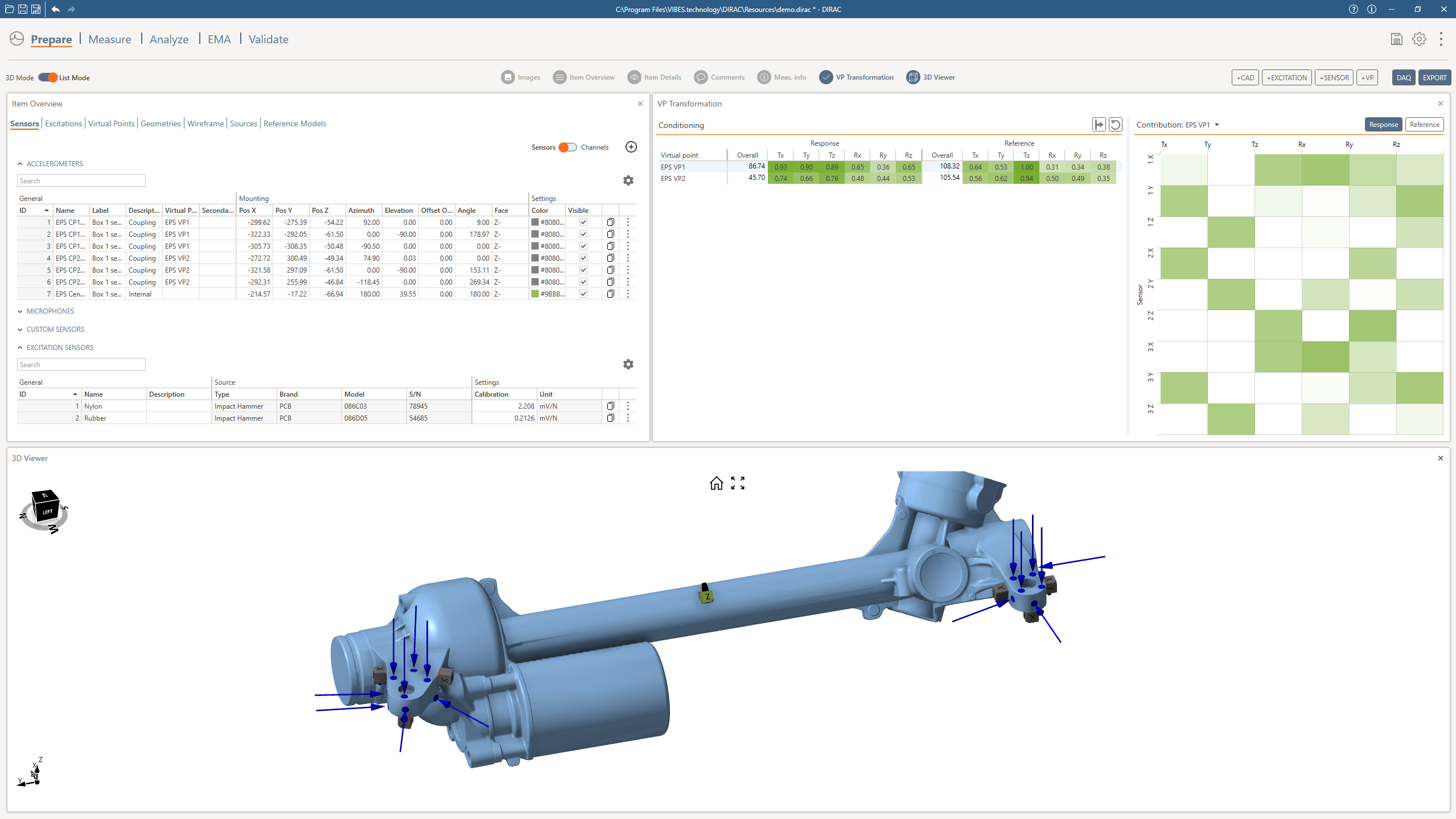
Prepare
Design the right experiment from the start
DIRAC helps engineers design high-quality experiments before any data is measured. A modern 3D environment brings geometry, sensors, excitations, and Virtual Points together in one place, reducing setup errors and improving traceability.
Key capabilities include:
- Interactive 3D environment for experiment design
- Direct visualization of CAE models for informed sensor placement
- Definition of sensors, impacts, shakers, and Virtual Points on the geometry
- Instant validation of degrees of freedom and measurement completeness
- Clear, traceable experiment setup as a foundation for accurate FRFs
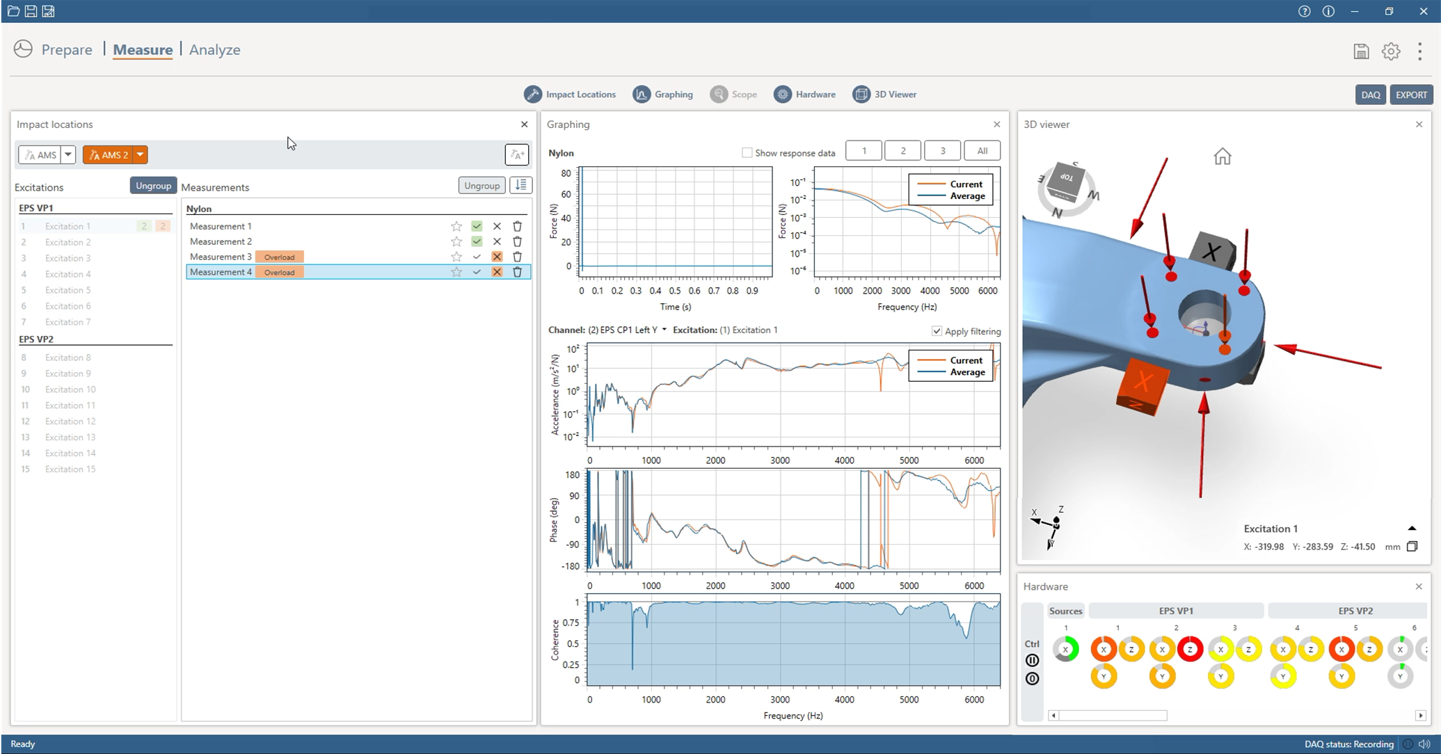
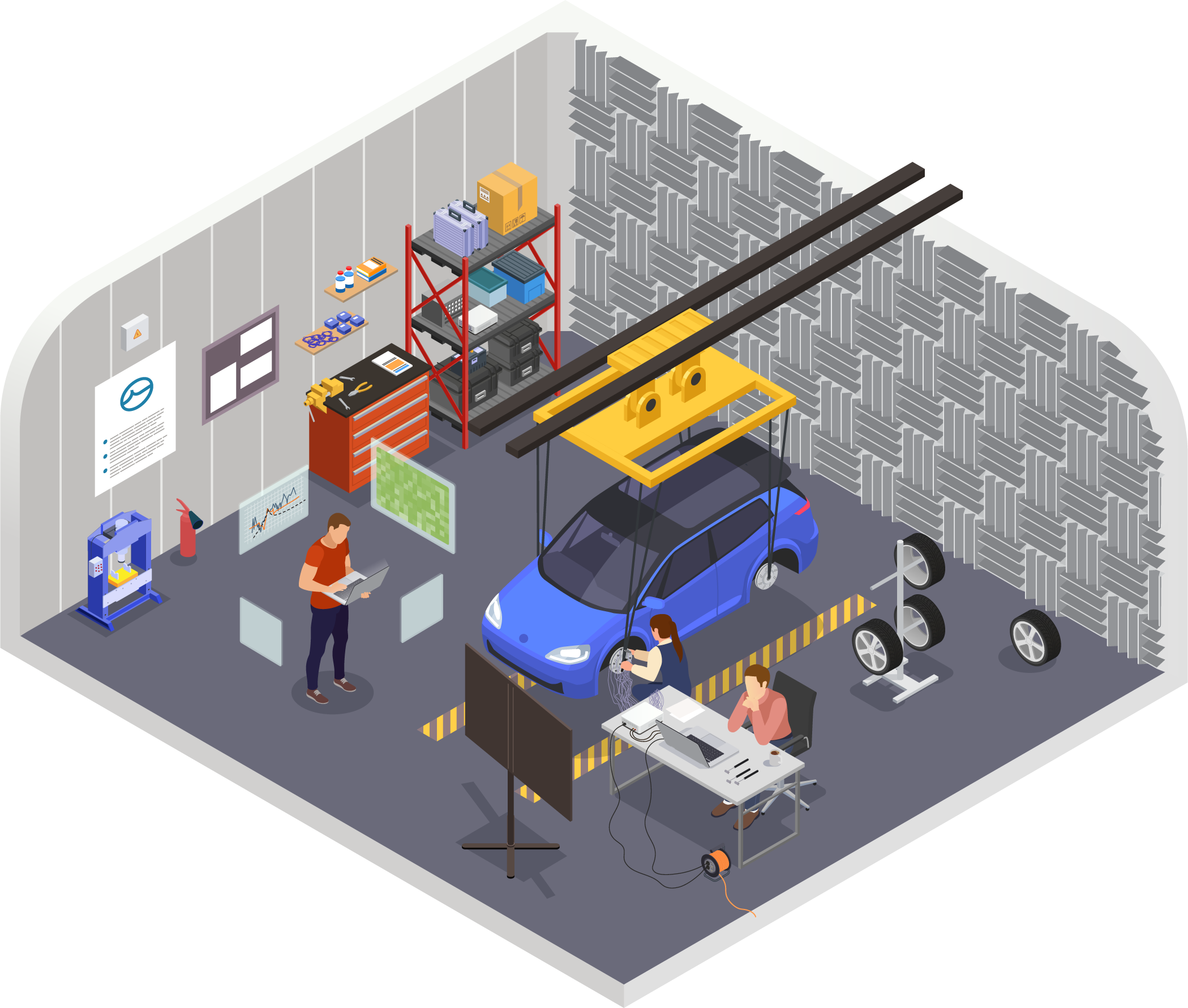
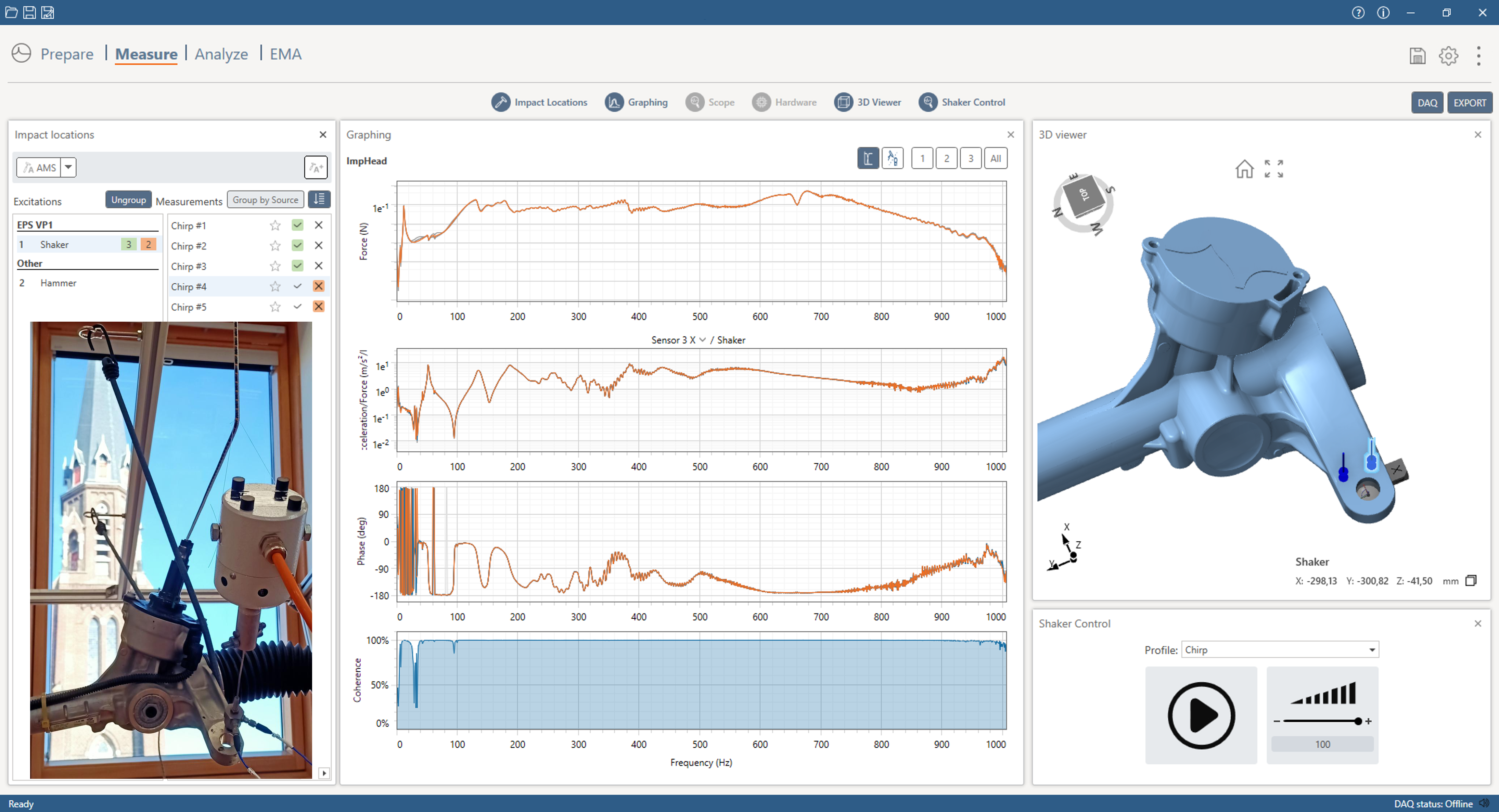
Measure
Acquire high-quality FRFs
During testing, DIRAC combines live measurement guidance with advanced algorithms to ensure data quality from the first attempt. Tight integration with PAK allows seamless acquisition, while automated checks prevent common measurement mistakes.
Key capabilities include:
- Live measurement and feedback during testing
- Seamless integration with PAK data acquisition
- Support for impact, shaker, and reciprocal NTF measurements
- Algorithms for false and inconsistent measurement detection
- Automatic selection and combination of the best measurements
- Efficient workflows that reduce rework and test time
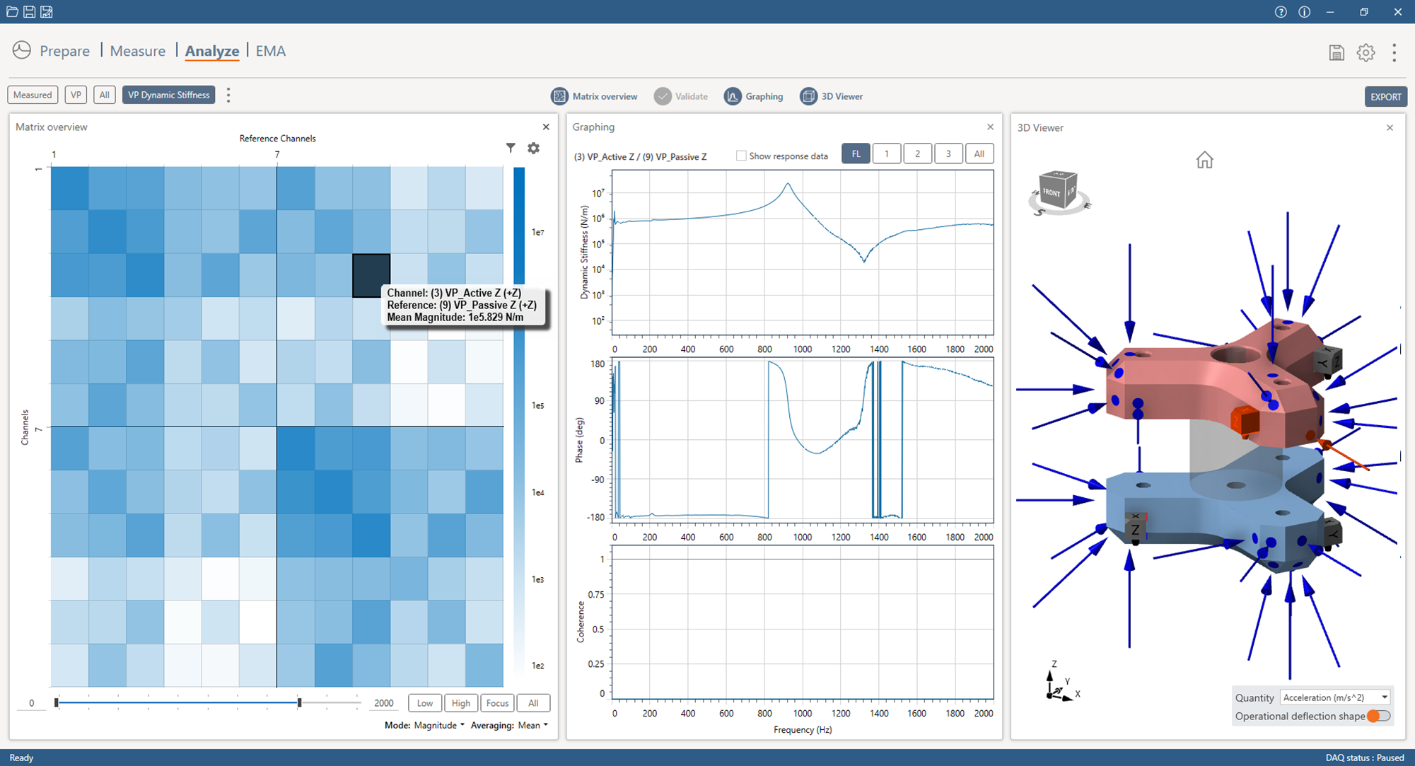
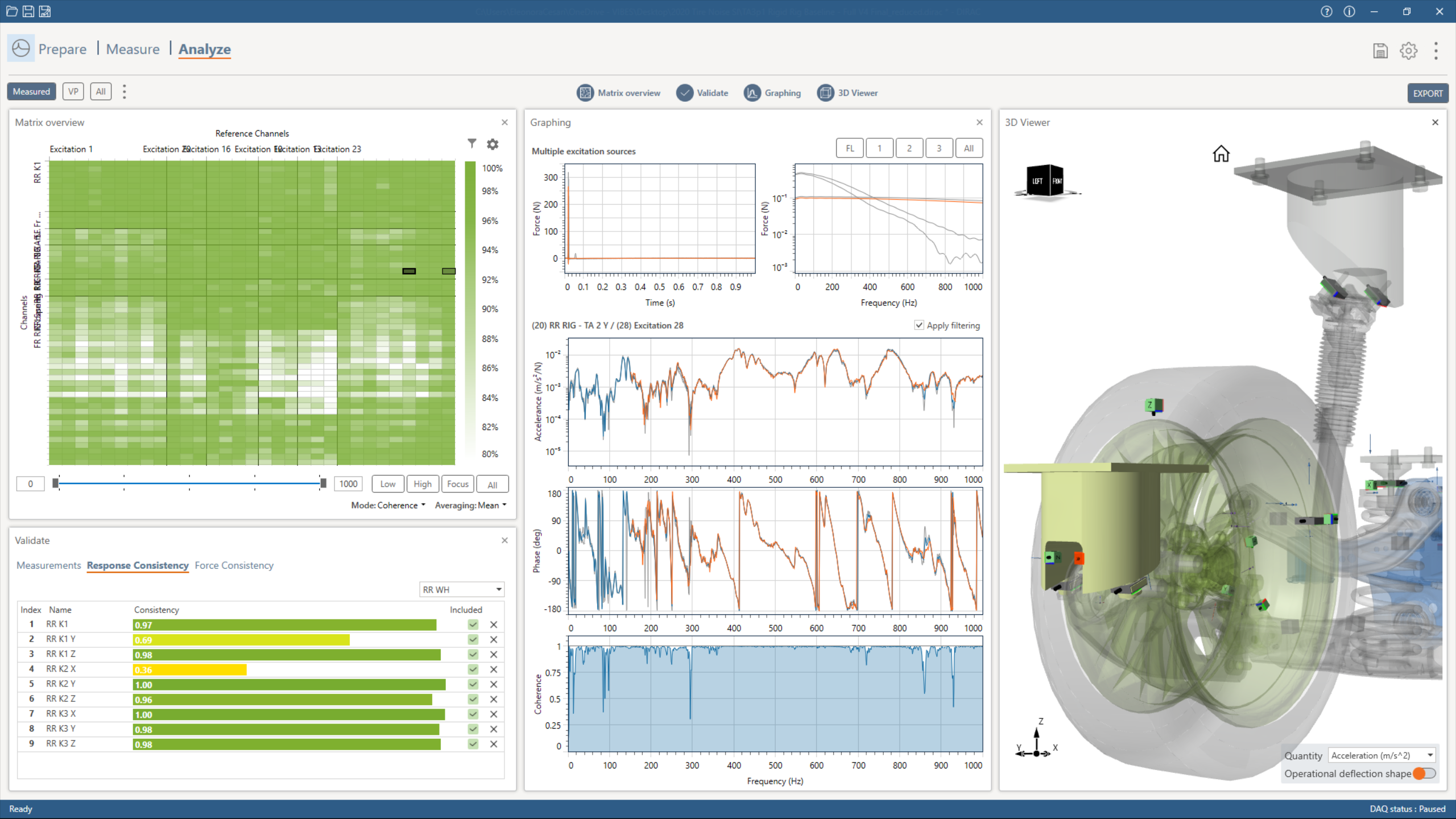
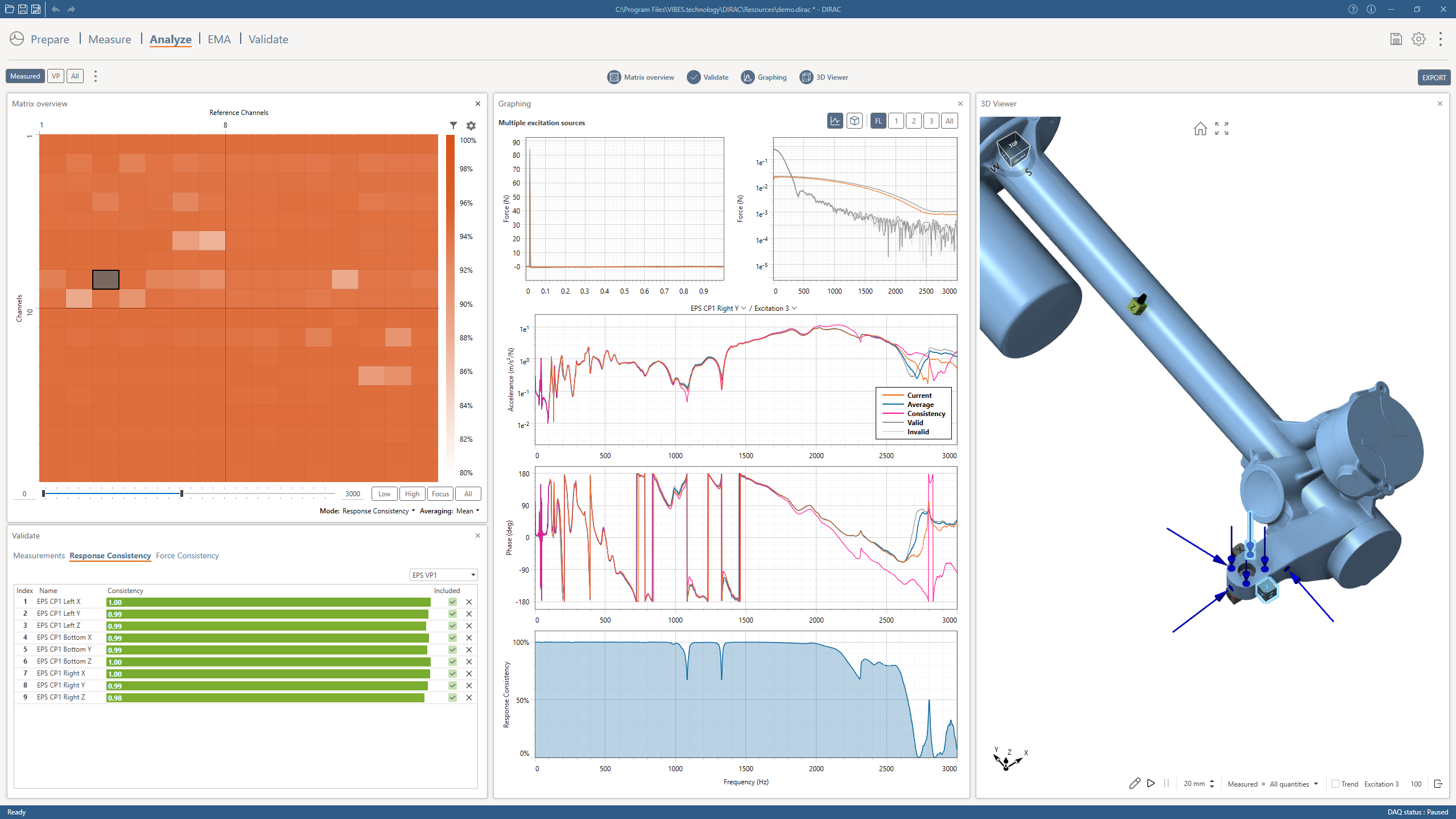
Analyze
Validate, interpret, and reuse your data
DIRAC applies advanced analysis directly to validated FRF measurements, turning test data into reliable engineering insight. Within a single workflow, engineers can create meaningful interfaces, extract dynamic behavior, and assess how accurately models represent the measured structure. This ensures that measurement results are immediately usable for simulation, validation, and further engineering work.
Available analyses include:
- Virtual Point (VP) transformation – Create physically meaningful interfaces from measured FRFs
- Modal analysis – Identify and interpret structural dynamics
- Model validation – Compare test data with CAE models
- Reciprocal NTF measurements – Verify transfer behavior and reciprocity
- Mount identification and fitting – Identify boundary conditions and mount properties
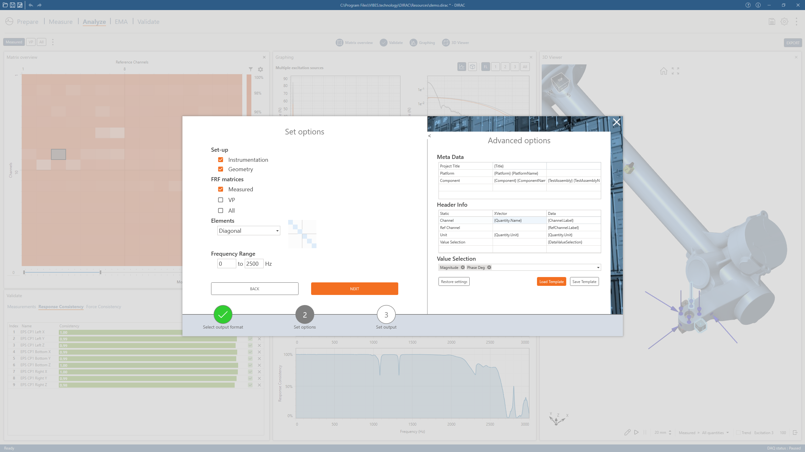
Export
Reuse your data across workflows
DIRAC ensures that validated measurement and analysis results can be seamlessly reused in downstream engineering workflows. FRFs, Virtual Point data, and derived results can be exported to widely used standardized formats such as Excel, HTMX, MATLAB, and UFF, making integration with existing analysis environments straightforward. In addition, DIRAC supports export to file formats that are native to VIBES’ SOURCE and COUPLE software products, enabling a smooth transition to source characterization, coupling, and system-level studies without data conversion or loss of traceability.
What Engineers Say
When Expertise Meets Application
Inspirational insights
Curious how DIRAC makes a difference in real engineering projects? Explore the articles below to see how advanced test-based modelling and Virtual Point techniques help teams overcome NVH challenges, improve model accuracy, and deliver reliable results faster than traditional FRF workflows.
Find out more
DIRAC: Measure Once. Use Everywhere.
DIRAC sets a new standard for test-based modelling and FRF measurement. Ready to go further? Learn how our services can accelerate your NVH programs, discover real-world applications in the DIRAC magazine, or explore every feature in the Product Guide.