VIBES & BMW: DS and component TPA applied to a fully electric BMW i4
Drivetrain acoustics play an important role in realizing a premium NVH experience in electric passenger vehicles. To achieve minimal sound pressure levels in the cabin under strenuous demands on development time and cost, engineers require a clear full-vehicle overview throughout the complete development process. In COUPLE, both measurements and already available subsystem models can be combined to full-vehicle models which can be improved continuously at all stages of the development process. This project shows this modular NVH engineering process based on Dynamic Substructuring and component Transfer Path Analysis (TPA) techniques, using experimental data obtained from a fully electric BMW i4 vehicle.
The project
This project has been carried out as part of the EUREKA EUROSTARS project. VIBES has, in collaboration with the Technical University of Munich (TUM) and the German car and motorcycle manufacturer BMW Group A.G., set the goal to develop COUPLE. In this software product, test-based models can be combined with models from simulations, offering a complete modular NVH approach. COUPLE allows you to assemble, predict and optimize your full-vehicle NVH design. This way, late-phase troubleshooting is avoided and fewer iterative design cycles are needed, saving time and resources.
In the development process of COUPLE, testing (in an industrial application) and further evolving the software is an important aspect. To that end, BMW has provided a BMW i4, measurement equipment and support during the measurements. The TUM has made their measurement lab available for measurements.
The full paper of the project can be found here.
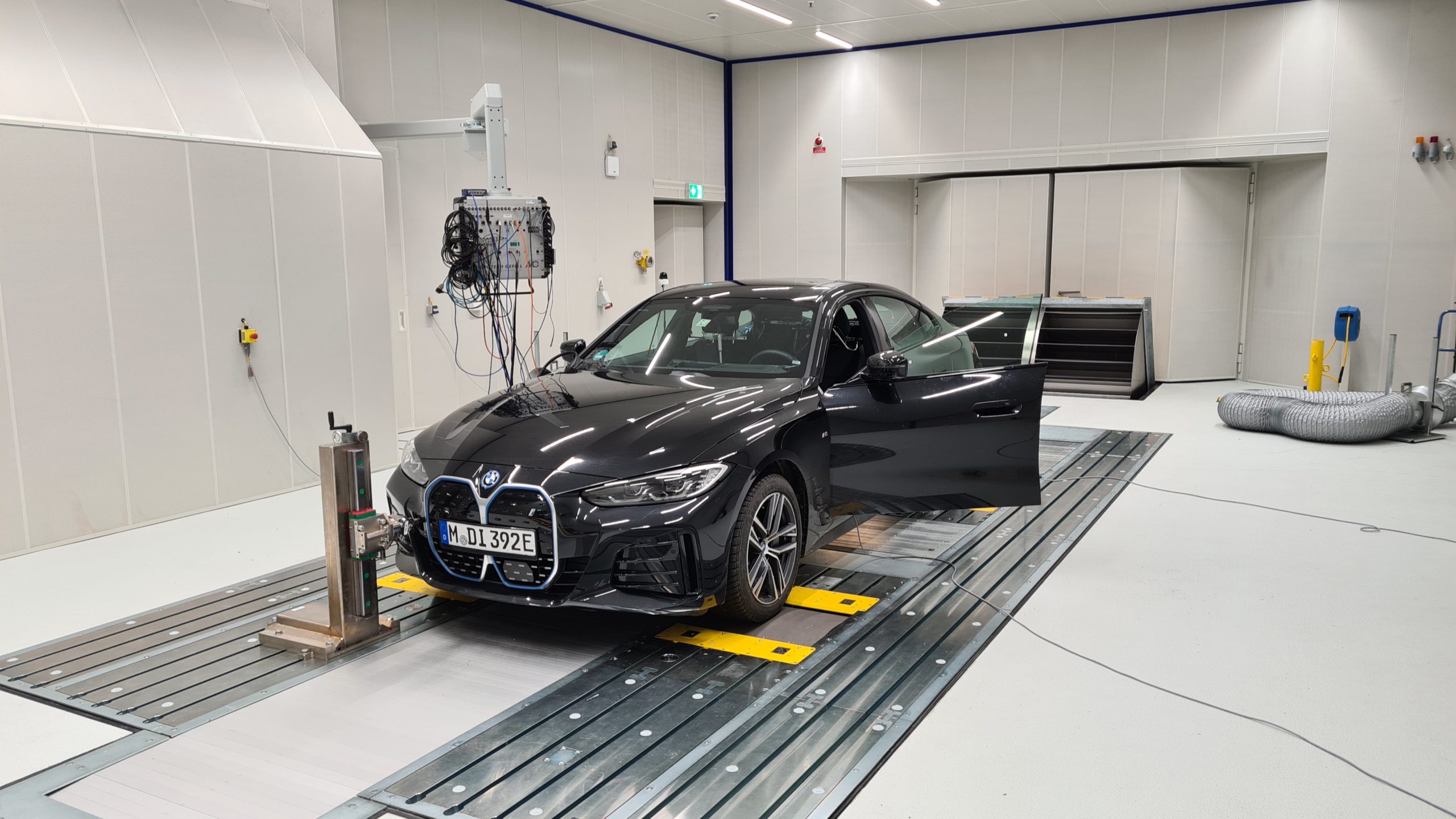
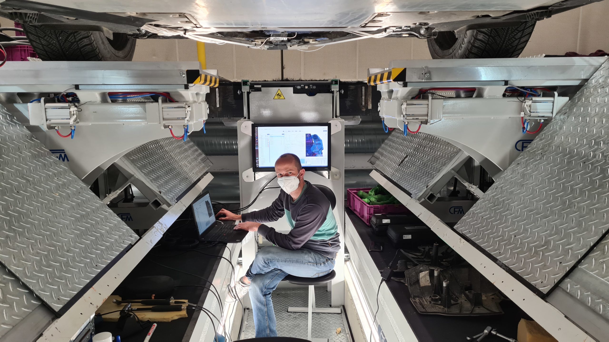
The BMW i4 in the NVH measurement lab at the Forschungsund Innovationszentrum of BMW Group AG in Munich
The goals
In the past, the full-vehicle NVH performance was mostly considered at either the early stage of the development, while deriving full-vehicle and subsystem requirements, or by the end of the process when full-vehicle prototypes are available. With this approach, during subsystem development a design gap appears. This design gap is likely to grow in the future, as OEMs aim to reduce costly prototyping. This means that full-vehicle models will be less available and if available, at a much later stage. Dynamic Substructuring (DS) and component TPA can provide useful insights within this design gap by using already available subsystem models and measurements; combining them to full-vehicle models which can be improved continuously at all stages of the development process.
In this project we aimed at grasping the solution for this design gap by means of Dynamic Substructuring, benefitting not only BMW, but also serving as an innovating step in the automotive branche.
Looking at a more specific scale, we aimed at testing COUPLE in an industrial application, with the intention to validate its funtionality and obtaining test data in order to further develop the software.
The approach
In this measurement campaign we measured the full-electric rear-wheel drive 2021 BMW i4, as shown in the figure above. This work focused on the vibrations generated by the Electric drive unit (EDU) and used sound pressure level in the vehicle cabin as well as accelerations on the driver’s seat-rail as the targets for evaluation. The EDU is the only power source of the BMW i4 and is mounted with four rubber bushings into a rear axle carrier (RAC). Two drive shafts and several cables and hoses are excluded as transfer paths. The RAC is mounted with again four rubber bushings to the vehicle trimmed body. Several suspension links, which connect the RAC to the wheel hubs, are excluded as transfer paths. Finally, the vehicle trimmed body (TMB) contained the targets: one triaxial accelerometer at the driver’s seat-rail and in total 6 microphones in the vehicle cabin (driver left + right, passenger left + right, the VIP-seat at the rear right and one in the center). So, in total we used eight rubber bushings of four different types in this project, also shown in the image below:
- EDU – RAC bushing front, 2x
- EDU – RAC bushing rear, 2x
- RAC – TMB bushing front, 2x
- RAC – TMB bushing rear, 2x
Transfer paths from the EDU up to the targets in the cabin, i.e. sound pressure at the driver’s ear and vibrations at the seat rail, were obtained through Dynamic Substructuring of the individual subsystem models using the Lagrange Multiplier Frequency Based Substructuring (LM-FBS) method. Transfer paths from the rear wheel hubs up to the targets in the vehicle were obtained from FRF measurements. The individual subsystem models were obtained through measurements using the Virtual Point Transformation in DIRAC.
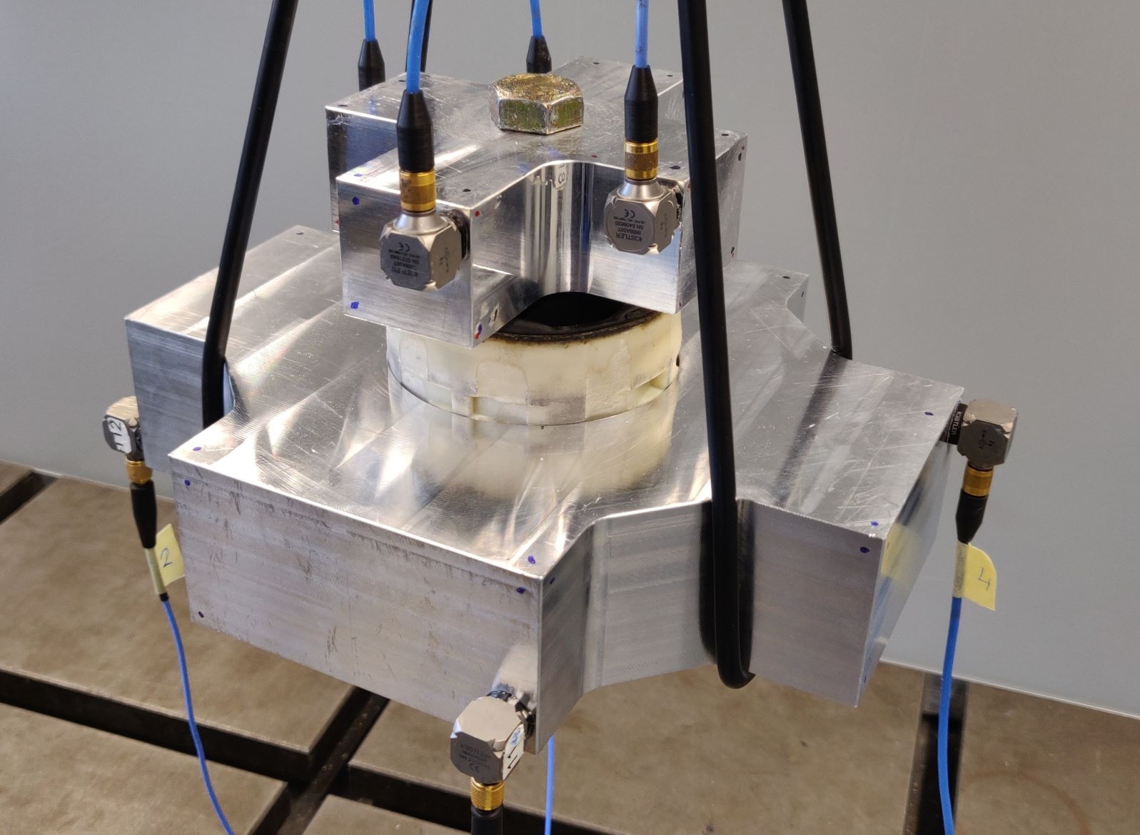
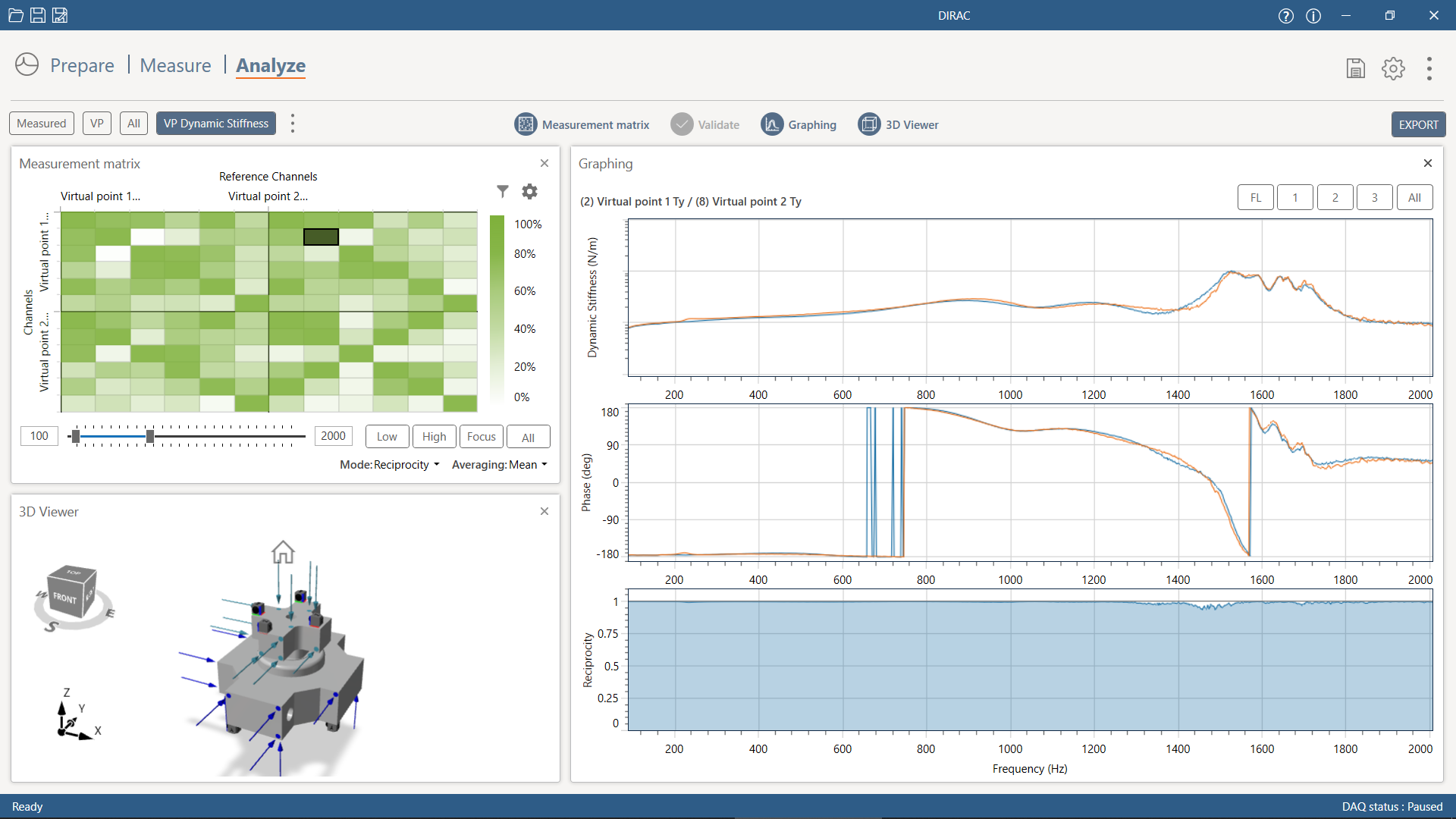
One of the advantages of using DIRAC, in combination with the CAD-geometries of the subsystems, is that all measurements could fully be prepared in a digital 3D environment. For each interface, a Virtual Point (VP) was defined with the right number of DoF (typically 6). The rubber bushings (left figure below) were modeled using the inverse-substructuring approach, which is also available in DIRAC (right figure below; click on the image to enlarge).
For each of the subsystems specific considerations have been made on the selection of interfaces and the measurement execution. The FRFs of the EDU are measured in free-free condition. The four connection points to the RAC are considered as interfaces. The two drive shafts and several cables and hoses are excluded from the subsystem model, but do add boundary conditions to the EDU in practice.
The FRF measurement of the RAC is also performed in free-free condition. The RAC has four interfaces to the EDU and four interfaces to the TMB. Several other interfaces are excluded as transfer paths in this project: both on the left and right side of the RAC four suspension links are excluded. On each side three of these suspension links connect directly to the wheel hub, while one link connects to both the spring-damper and the wheel hub. The excluded interfaces do add boundary conditions to the RAC in practice.
The FRF measurement of the TMB is performed with the EDU, the RAC and the rear wheels dismounted. Therefore, the rear-side of the TMB is resting on rubber blocks during the measurement.
All inputs where then imported in COUPLE (see the figure below), allowing us to generate NVH predictions based on the modular subsystem models and the equivalent force descriptions.
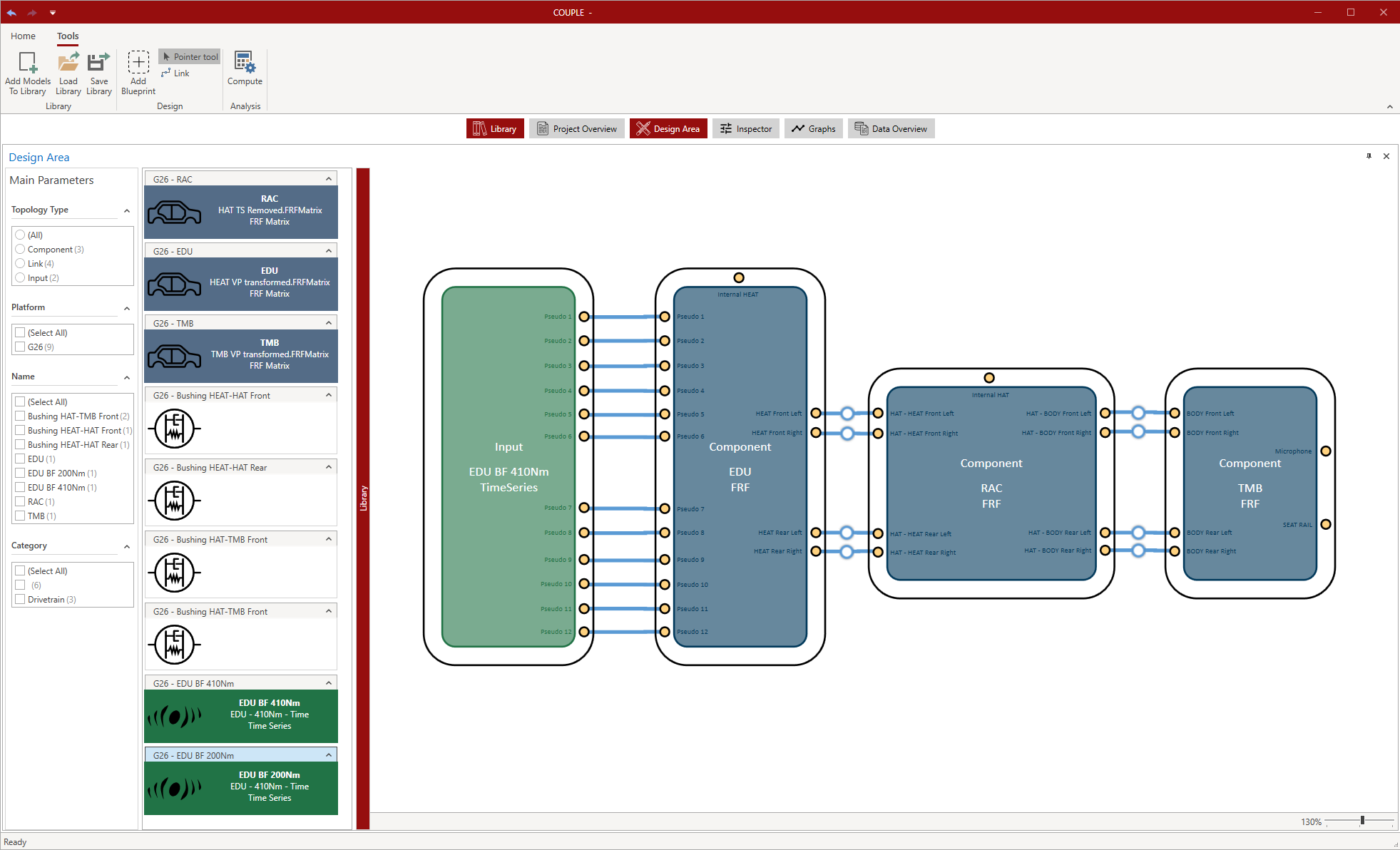
COUPLE is used to apply DS and generate the full-vehicle NVH predictions. Using a 2D-environment connections between the subsystems are easily created and compliant coupling conditions are added at the interfaces. Connections are made visually from interface to interface, the software automatically matches the individual DoFs.
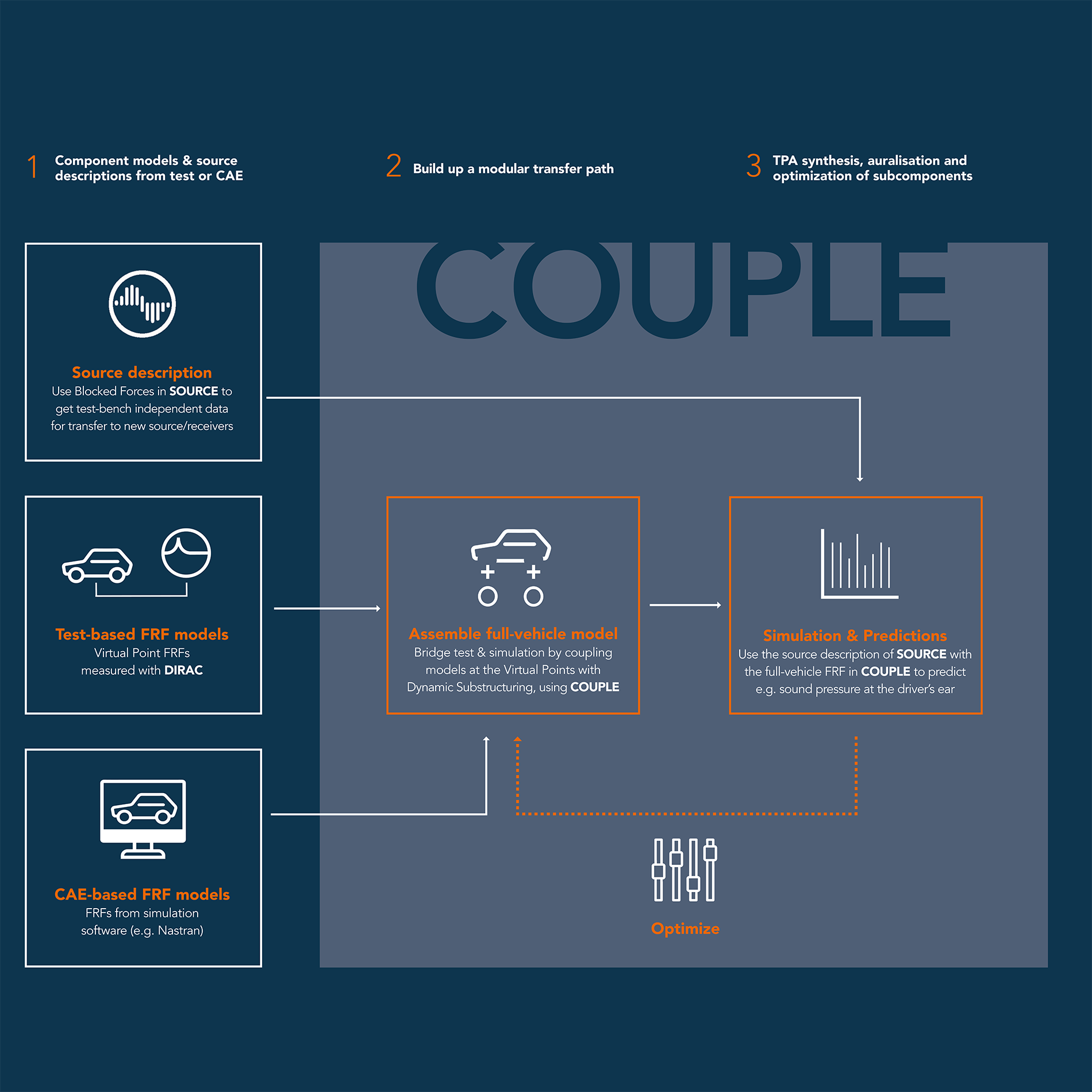
In this case, data generated in DIRAC was used as input for performing predictions in COUPLE. However, also simulated models from your favorite CAE software can be inported to COUPLE to generate a full-vehicle model. Moreover, COUPLE works with source characterization data from SOURCE, allowing you to simulate and further optimize your NVH design. The overview image below shows how VIBES’ software products fit together for a full-vehicle modular NVH design.
The full-vehicle measurements have been performed to obtain data at the on-board validation sensor on the RAC, at the interior microphones and at the seat-rail accelerometer. Two measurements have been performed: 1) operational runs with the rear-wheels on a dyno and 2) impact measurements on the pseudo force locations at the EDU and at the rear wheel hubs.
The operational measurements to characterize the EDU have been performed with the EDU mounted in-situ in the vehicle, while the full-vehicle was running with the rear-wheels on a dyno. Hereby, a second vibration source is introduced which originates from the tires rolling on the drums of the dyno.
Also, due to the tight packaging of the EDU it was not possible to use hammer impacts to excite the EDU around the connection points to the RAC, which one would typically do to obtain Blocked Forces. Therefore, pseudo forces have been used as a source characterization approach. Twelve impacts have been placed in various directions at the bottom of the EDU (because the sides and top of the EDU could not be reached due to the tight packaging). Indicator sensors u4 have been placed on the EDU: two triaxial accelerometers close to each of the four EDU-RAC interfaces.
Besides noise measurements, three operational conditions have been measured during a run-up in speed: a slow (50 Nm), a medium (200 Nm) and a wide-open throttle (WOT) acceleration (410 Nm). The results shown in this project are based on the WOT measurement.
The results
This work showed how Dynamic Substructuring and component TPA techniques can be applied on a full-electric vehicle to obtain modular test-based NVH predictions, using specialized software packages to simplify the process and to provide the necessary quality checks throughout the process.
When the accessibility for in-situ source characterization is limited, this work showed how pseudo forces can be used as an equivalent force description instead of Blocked Forces at the interface points.
It was shown, that for the operational conditions considered in this work, the BMW i4 EDU has a limited contribution to the observed sound and vibrations in the cabin. Which is a good thing, as the BMW i4 is already on the market. It shows however, that we can successfully use COUPLE to do DoF matching and make predictions. This means that by using COUPLE in the engineering design process, the same (or even better) outcomes regarding e.g. the sound pressure levels produced by an EDU could be achieved, probably in a faster and less expensive way. This confirms one of COUPLE’s greatest benefit cq. reason for existence.
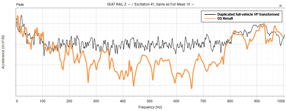
Furthermore, when obtaining subsystem models through free-free FRF measurements, this project showed the relevance of including the boundary conditions which exist in the vehicle and might add damping to the models. Although the general trend was followed, the DS results show much less damping versus the full-vehicle reference.
The first figure below shows an FRF with the response at the driver’s seat rail due to an impact on the EDU. The DS result is shown in orange, the validation measurement performed on the full-vehicle is shown in black. Due to the double isolation stage, the transfer of the validation measurement is in large part unobservable in impact testing. The second figure below shows the coherence of multiple impacts from the FRF measurement. The low coherence from 100-800Hz indicates that the measurement is dominated by noise. Using DS, one can obtain results below the noise floor.
Validation of operational predictions including full-vehicle Dynamic Substructuring FRFs is difficult, due to presence of multiple sources which are not included in the Dynamic Substructuring model, such as tirenoise from the dyno.
The test data that is obtained from the measurements in this project is used for the development of software catered to industrial process. Also, from the process we obtained valuable feedback to improve the product(s). For instance in the user-friendliness of some features and the overall workflow of the software. All-in all, a very valuable project outcome in the development process of COUPLE!
More COUPLE
The official release of COUPLE will take place in the fall of 2022. If you already want to experience COUPLE, it’s possible for you to participate in the testing of our closed-beta version, get a demo of the closed-beta version and/or subscribe for a full version demo of COUPLE in the fall of 2022. Opt-in on this page or contact us for more information.


