Characterisation of an Electromagnetic Roll Control with Blocked Forces
23 July 2020
Blocked Forces have made a big upswing as source characterisation method in the past few years. OEMs are pushing this method through in component specifications and as a result, suppliers are answering to this trend by obtaining this competence and implementing this in their respective workflows. High quality blocked forces rely deeply on high quality test models, which is where DIRAC makes a real difference. A great example is the one of ZF, a well-established German automotive supplier and how they prepared for Blocked Forces in a collaboration project.
The scope
The purpose of this project for ZF has been straightforward. Getting prepared for future requests on blocked forces by means of a general investigation. This general investigation has covered the applicability of blocked forces, as well as different Transfer Path Analysis (TPA) methods in a more general sense.
As a result, three scope items were defined for this project. Each contributing to the overall picture of these methods:
- Required Degrees of Freedom (DoFs): Should rotational DoFs be included and is a virtual point transformation beneficial when this is not the case?
- Quality indicators: What are good indicators for validating the data obtained on vehicle or testbench?
- Transferability of Blocked Forces: Can blocked forces be used as source characterisation independent of the test environment?
The Electromagnetic Roll Control (ERC) unit in a vehicle would provide a good testing ground for the above.
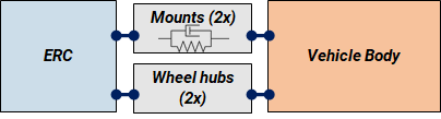
Schematic display of the mounting situation of the ERC in the vehicle
Obtaining data and performing analyses
Component models of the vehicle with ERC and the ERC in an alternative test setup were obtained by measuring in DIRAC. For the purpose of performing a classical TPA, a model of the vehicle without the ERC was obtained in addition, also with DIRAC.
Configurations with virtual points including and excluding rotational DoFs – as well as a configuration with only 3-DoF measurement – were combined with operational data having the ERC ‘active’ to obtain blocked forces. The variously obtained blocked have formed the basis for the majority of analyses. Each set was used to synthesise an in-vehicle response for comparison with a validation signal.
The upside of using DIRAC
We used our measurement software DIRAC with a live connection to a PAK MK2 measurement system to generate high-quality component models. As all required quality information was live available, any potential measurement errors could be spotted and solved directly. This allowed for a “first-time-right” workflow resulting in component models with high-quality virtual point information. CAD models of the subframe and ERC were readily available for this project, resulting in a controlled placement of sensors and impact positions for the FRF measurements. Also, preparation of the measurement setup was done in DIRAC on forehand, not wasting valuable measurement time.
In the remaining analyses SOURCE was used. Since both programs have embraced the virtual point technology the transition from measuring to analysis was fast and seamless. Thanks to the flexibility in this process we were able to efficiently set up and compare TPA results using different interface setups (e.g. with and without rotational DoFs).
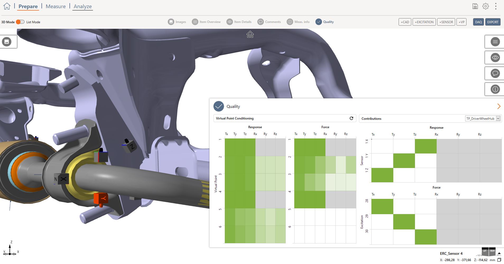
Preparing measurements in DIRAC
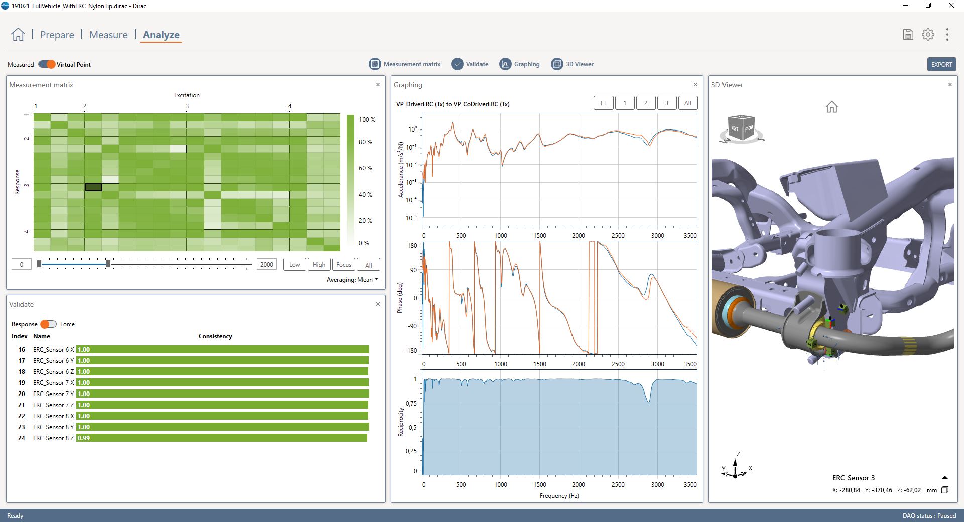
Measuring in DIRAC. The green matric overview is filled with quality indicators
A solid approach towards Blocked Forces
Some valuable lessons were learned during the course of this project. The insights on each of the respective scope items have led to a good physical understanding of the entire vehicle system. Regarding the scope items, the key take-aways were:
- Required Degrees of Freedom (DoFs): Including rotational DoFs improved results in the whole frequency range, but in particular for the higher frequencies (which was > 600 Hz for this project). Not using any form of VP, but solely three impacts and one triax-accelerometer led to unreliable results.
- Quality indicators: The above was confirmed by checking the Interface Completeness. Furthermore, passivity, symmetry and consistency proved to be useful quality indicators on the FRF model.
- Transferability of Blocked Forces: Blocked forces obtained on a different test setup proved to be accurate for the validation of in-vehicle responses, which makes these blocked forces transferable.
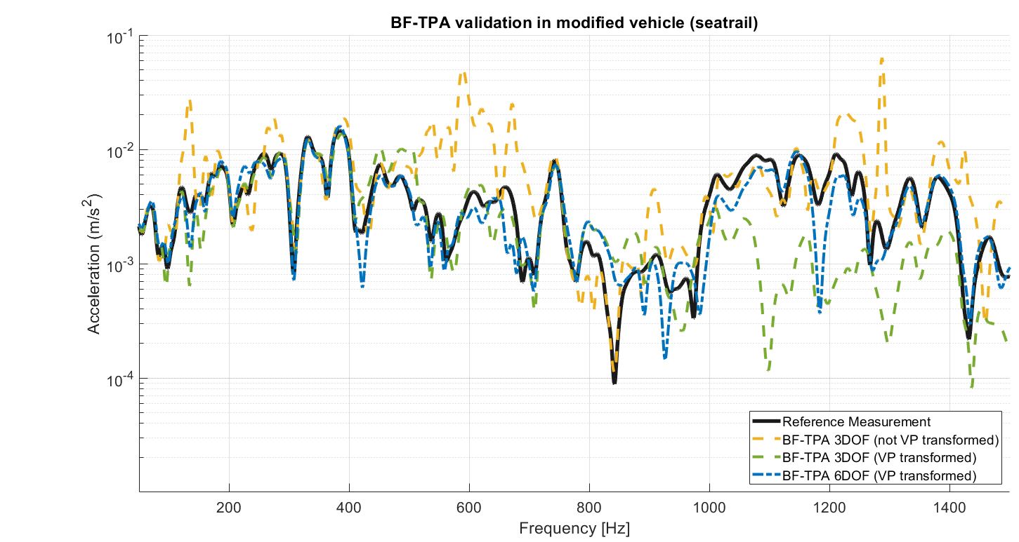
Result comparison for various interface definitions (with and without VP transformation).
Future-proof
This case was also described in our Source Characterization whitepaper, together with the theory about this topic. Download the paper or choose one of the blue buttons below for more information and cases.