Frequency Based Substructuring Applied to Electric Drivetrains
22 January 2021
Virtually optimizing and selecting the best components to reduce NVH issues can be done with test-data using Frequency Based Substructuring (FBS). After the success obtained in the Eurostar program, VIBES is working towards the creation of a software to implement this method. But what is FBS and what advantages does it bring? Let’s find them out in this article that describes a successful application of FBS on an electric drivetrain. The full project has been developed in collaboration with BMW.
The component
To show the potential of FBS we performed a study on an electrical drivetrain. In the electric assembly, 3 subsystems can be distinguished: the EDU (Electric Drive Unit), the RAC (Rear Axle Carrier) and the TMB (the bodywork or “trimmed-body”). A total of 8 coupling points can be identified: each of them has been represented as an elastic mount. Figure 1(a) shows the original full-vehicle assembly, for which operational run-up measurements have been conducted. Figure 1(b) shows the three-stage FBS model, which displays the substructuring as a chain of the 3 subsystems and the 8 coupling points..

Figure 1: Schematic overviews of the electric drivetrain assembly.
The goal
To show that FBS can be used to accurately predict the NVH performance, we studied the acoustics of an electrical vehicle. To do so, individual component models obtained from tests and FE-simulations have been used and combined with FBS. Later, the results obtained in such way have been compared with the measurements of the assembled system as a validation. Finally, a parameter variation study was also performed, to show the possibilities of this method.
The method
To perform the FBS, it is necessary to obtain the models of the 3 main subsystems (EDU, RAC and TMB) as well as models of the mounts. The latter are experimentally calculated using the inverse substructuring technique. This allows to know the dynamic stiffness of the mounts up to kHz levels, which is consistently higher than what usually provided by suppliers. models of the EDU, RAC and TMB are also originated from measurements. However, FE models of the drivetrain housing, the RAC and the connecting points to the car body were available, so they have been used to show the feasibility of a hybrid approach.
To ensure that the coupling of the subsystems is correct, Virtual Points are used. A Virtual Point is a 6-DoF point which can be obtained from both computer simulations and experiments (an example of Virtual Point obtained from our software DIRAC is shown in Figure 2). Equivalent forces are calculated at the interface between the drivetrain housing and the rubber bushings, using the free accelerations method. Afterwards, they are applied to the corresponding DOFs of the assembled system.

Figure 2: Virtual Point obtained with DIRAC.
The result
The resulting synthesis for the structure borne noise of the hybrid simulation can now be compared with the validation measurements. In Figure 3 the hybrid simulation results are shown in the upper row of the figure and the validation measurements are shown in the lower row. It can be seen that the match is really good overall and only the accelerations at the car body in the rear are underestimated compared to the validation measurement, as shown in the red circles.
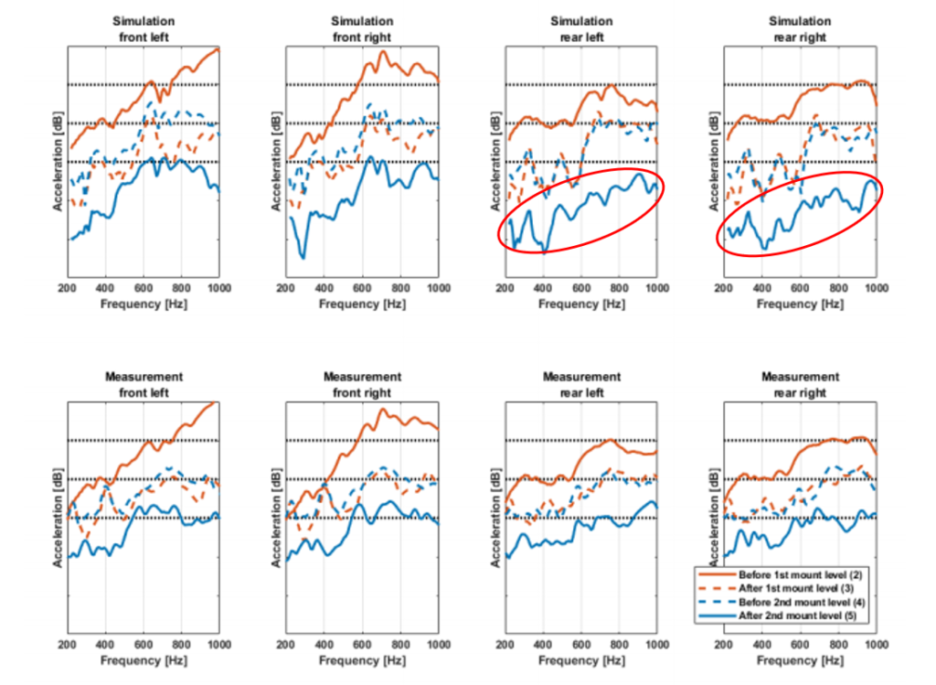
Figure 3: Validation of the structure borne noise. The numbers in the legend refer to the numbers used in Figure 1(b)
The benefits of Frequency Based Substructuring
- With FBS it is possible to exchange substructures and directly simulate the dynamics of the new system, leaving all other subsystems unchanged. In the study, the FEM model of the axle carrier has been changed multiple times using different values for the elasticity modulus and the density. These two parameters have been scaled respectively up and down with a specific amount. This was done to show the possibilities of the method and therefore one of the advantages of FBS. The results are shown in Figure 4.
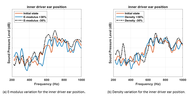
Figure 4: Parameter variation of the elasticity modulus and the density of the rear axle carrier
- FBS allows for the combination of subsystem models that get assembled to form a full vehicle model.
- The subsystems dynamics can either originate from finite element models or from component or subsystem measurements, allowing for a hybrid approach development.
- The full-vehicle model, simulated through FBS, can be used to close the gap in full-vehicle analysis and responsibility between the early-stage conception phase and the first actual prototype in hardware.
- Subsystem FRFs/NTFs are typically obtained at higher signal-to-noise ratios (SNR) then full-vehicle FRFs/NTFs, and thus better overall quality can be ensured.
More info
Do you want to know more? Get in touch with VIBES or read more cases, using the buttons below! You can also download the full paper here!